
Page 266 - Fiber Bragg Gratings
P. 266
6.2 The Fabry-Perot and moire band-pass filters 243
n eff is a function of wavelength. For an equivalent fiber-grating-based FP
interferometer, the thickness d becomes a function of wavelength, and
only at the peak reflectance is the FSR largest. The effective thickness
is the separation between the inner edges of the gratings plus twice the
effective length of the gratings. Off resonance, the penetration into the
grating is greater than on-resonance, leading to a bigger thickness. There-
fore, at the edges of the FP bandwidth, the FSR becomes smaller.
The first in-fiber grating FP filter was reported by Huber [24]. A
transmission bandwidth of 29 pm was reported. Further multi-band-pass
in-fiber FP resonators have also been demonstrated [25]. In the latter
report, a 100-mm-long FP interferometer was fabricated with two 95.5%
reflecting gratings. A finesse of 67 was achieved with the free spectral
range of 1 GHz and a pass bandwidth of 15 MHz. In order to measure
the transmission spectrum of the FP, a piezoelectric stretcher was used
to scan the fiber etalon in conjunction with a fixed frequency DFB laser
source operating within the bandwidth of the grating band stop, at a
wavelength of 1299 nm. A peak transmission of ~86% of the fringe maxi-
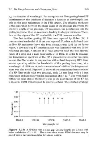
mum was also noted. Figure 6.13 shows the transmission characteristics
of a FP filter made with two gratings, each 0.5 mm long with a 5 mm
4
separation and a refractive index modulation of 2 X 10~ . The weak ripple
within the band-stop of the filter is due to the poor finesse of the FP but
is ideal in WDM transmission to control solitons. The shortest gratings
Figure 6.13: A FP filter with a 5-mm gap. Grating lengths are 0.5 mm with
4
index modulation of 2 X 10~ . The arrows show where WDM channels may be
placed within the band-pass filter for soliton guiding.