
Page 270 - Fiber Bragg Gratings
P. 270
6.3 The Michelson interferometer band-pass filter 247
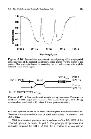
Figure 6.16: Transmission spectrum of a moire grating with a single period
cosine envelope of the modulation refractive index profile over the length of the
grating. This grating is formed by colocating two chirped gratings with slightly
different center wavelengths.
Port 2: OUTPUT 25% at ^
Figure 6.17: A fiber coupler with a single grating in one arm. The output in
port 2 is 25% of the input power in port 1. The transmitted signal at the Bragg
wavelength at port 3 is (1 — R\ where R is the grating reflectivity.
This arrangement works as an effective band-pass filter despite the loss.
However, there are methods that be used to eliminate the insertion loss
of this filter.
With two identical gratings, one in each arm of the MI, 100% of the
reflected light can be routed to port 2. The principle of operation was
originally proposed by Hill et al. [34], for a grating in a loop mirror