
Page 271 - Fiber Bragg Gratings
P. 271
248 Chapter 6 Fiber Grating Band-pass Filters
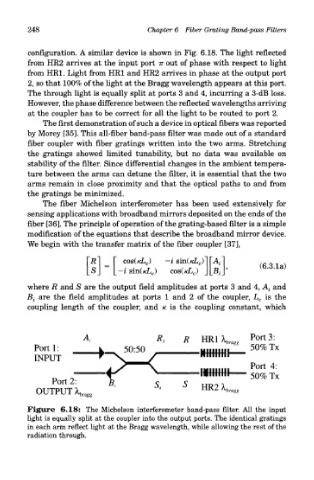
configuration. A similar device is shown in Fig. 6.18. The light reflected
from HR2 arrives at the input port TT out of phase with respect to light
from HR1. Light from HR1 and HR2 arrives in phase at the output port
2, so that 100% of the light at the Bragg wavelength appears at this port.
The through light is equally split at ports 3 and 4, incurring a 3-dB loss.
However, the phase difference between the reflected wavelengths arriving
at the coupler has to be correct for all the light to be routed to port 2.
The first demonstration of such a device in optical fibers was reported
by Morey [35]. This all-fiber band-pass filter was made out of a standard
fiber coupler with fiber gratings written into the two arms. Stretching
the gratings showed limited tunability, but no data was available on
stability of the filter. Since differential changes in the ambient tempera-
ture between the arms can detune the filter, it is essential that the two
arms remain in close proximity and that the optical paths to and from
the gratings be minimized.
The fiber Michelson interferometer has been used extensively for
sensing applications with broadband mirrors deposited on the ends of the
fiber [36]. The principle of operation of the grating-based filter is a simple
modification of the equations that describe the broadband mirror device.
We begin with the transfer matrix of the fiber coupler [37],
where R and S are the output field amplitudes at ports 3 and 4, A i and
B t are the field amplitudes at ports 1 and 2 of the coupler, L c is the
coupling length of the coupler, and K is the coupling constant, which
Figure 6.18: The Michelson interferometer band-pass filter. All the input
light is equally split at the coupler into the output ports. The identical gratings
in each arm reflect light at the Bragg wavelength, while allowing the rest of the
radiation through.