
Page 274 - Fiber Bragg Gratings
P. 274
6.3 The Michelson interferometer band-pass filter 251
bandwidths of the two gratings are identical (nominally identical lengths
and refractive index modulation amplitudes), the path difference may
drift within the lifetime of the device, or the Bragg wavelengths may not
be identical, or may change with time.
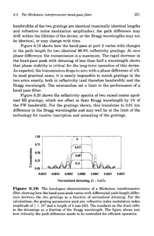
Figure 6.19 shows how the band-pass at port 2 varies with changes
in the path length for two identical 99.8% reflectivity gratings. At zero
phase difference, the transmission is a maximum. The rapid decrease in
the band-pass peak with detuning of less than half a wavelength shows
that phase stability is critical for the long-term operation of this device.
As expected, the transmission drops to zero with a phase difference of 77/2.
In most practical cases, it is nearly impossible to match gratings in the
two arms exactly, both in reflectivity (and therefore bandwidth) and the
Bragg wavelength. The mismatches set a limit to the performance of a
band-pass filter.
Figure 6.20 shows the reflectivity spectra of two raised cosine apod-
ized MI gratings, which are offset in their Bragg wavelength by 1% of
the FW bandwidth. For the gratings shown, this translates to 0.01 nm
difference in the Bragg wavelengths and may well be at the limit of the
technology for routine inscription and annealing of the gratings.