
Page 278 - Fiber Bragg Gratings
P. 278
6.3 The Michelson interferometer band-pass filter 255
6.3.1 The asymmetric Michelson multiple-band-pass
filter
Figure 6.19 showed how output power in port 1 varies with path difference
$. The reflected power within the entire grating spectrum is exchanged
between port 1 and 2 so long as the detuning
where AA g is the FWFZ bandwidth of the grating. With larger path differ-
ences, n eff&Lf = rief^Lft - Lfz), the phase variation 8 as a function of
wavelength, according to Eq. (6.3.4), becomes substantial across the band-
width of the grating. Thus, the single uniform band pass of the filter
begins to split into a sinusoidal wavelength with wavelength, restricted
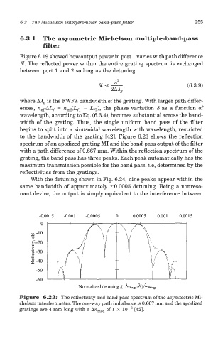
to the bandwidth of the grating [42]. Figure 6.23 shows the reflection
spectrum of an apodized grating MI and the band-pass output of the filter
with a path difference of 0.667 mm. Within the reflection spectrum of the
grating, the band pass has three peaks. Each peak automatically has the
maximum transmission possible for the band pass, i.e, determined by the
reflectivities from the gratings.
With the detuning shown in Fig. 6.24, nine peaks appear within the
same bandwidth of approximately ±0.0005 detuning. Being a nonreso-
nant device, the output is simply equivalent to the interference between
Figure 6.23: The reflectivity and band-pass spectrum of the asymmetric Mi-
chelson interferometer. The one-way path imbalance is 0.667 mm and the apodized
3
gratings are 4 mm long with a A/i mod of 1 X 1CT [42].