
Page 275 - Fiber Bragg Gratings
P. 275
252 Chapter 6 Fiber Grating Band-pass Filters
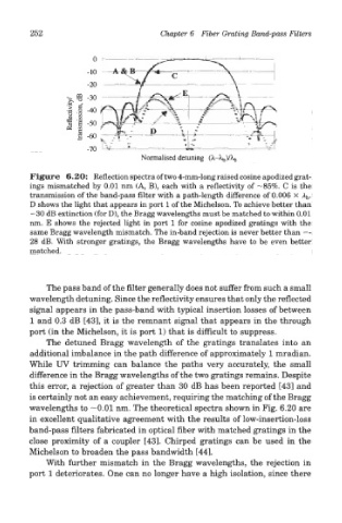
Figure 6.20: Reflection spectra of two 4-mm-long raised cosine apodized grat-
ings mismatched by 0.01 nm (A, B), each with a reflectivity of —85%. C is the
transmission of the band-pass filter with a path-length difference of 0.006 X A b.
D shows the light that appears in port 1 of the Michelson. To achieve better than
—30 dB extinction (for D), the Bragg wavelengths must be matched to within 0.01
nm. E shows the rejected light in port 1 for cosine apodized gratings with the
same Bragg wavelength mismatch. The in-band rejection is never better than —
28 dB. With stronger gratings, the Bragg wavelengths have to be even better
matched.
The pass band of the filter generally does not suffer from such a small
wavelength detuning. Since the reflectivity ensures that only the reflected
signal appears in the pass-band with typical insertion losses of between
1 and 0.3 dB [43], it is the remnant signal that appears in the through
port (in the Michelson, it is port 1) that is difficult to suppress.
The detuned Bragg wavelength of the gratings translates into an
additional imbalance in the path difference of approximately 1 mradian.
While UV trimming can balance the paths very accurately, the small
difference in the Bragg wavelengths of the two gratings remains. Despite
this error, a rejection of greater than 30 dB has been reported [43] and
is certainly not an easy achievement, requiring the matching of the Bragg
wavelengths to —0.01 nm. The theoretical spectra shown in Fig. 6.20 are
in excellent qualitative agreement with the results of low-insertion-loss
band-pass filters fabricated in optical fiber with matched gratings in the
close proximity of a coupler [43]. Chirped gratings can be used in the
Michelson to broaden the pass bandwidth [44].
With further mismatch in the Bragg wavelengths, the rejection in
port 1 deteriorates. One can no longer have a high isolation, since there