
Page 280 - Fiber Bragg Gratings
P. 280
6.3 The Michelson interferometer band-pass filter 257
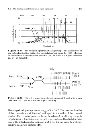
Figure 6.25: The reflection spectrum of each grating (1 and 2) measured in
situ by bending the fiber in the other port to induce loss: hence the —25% reflection.
The normalized band-pass filter spectrum (BP) as a result of a path difference
ALf of -1.33 mm [42].
Figure 6.26: Chirped gratings in configurations A and B, each with a path
imbalance of AZy but with reversed sign of the chirp.
3
The unapodized gratings have a Arc mod of 1 X 10~ . The pass bandwidths
of the channels are all identical and equal to the width of the channel
spacing. The repeated pass bands can be adjusted by altering the path
imbalance; in a demonstration, the paths were adjusted by stretching one
arm of the interferometer to fit a grid of 1.1 or 2.2 nm using two 15-nm-
bandwidth chirped gratings [45].