
Page 276 - Fiber Bragg Gratings
P. 276
6.3 The Michelson interferometer band-pass filter 253
is less overlap between the bandwidths of the gratings. The conditions
approach the case of a single grating in the coupler arm, when there is
no overlap of the grating spectrum. Thus, at least 25% of the input power
appears at both ports 1 and 2. While the rejection becomes poor, the band-
pass suffers because the bandwidth decreases as a direct result of the
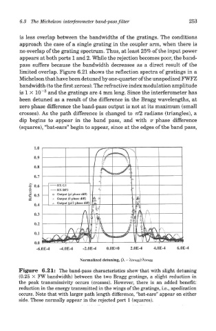
limited overlap. Figure 6.21 shows the reflection spectra of gratings in a
Michelson that have been detuned by one-quarter of the unapodized FWFZ
bandwidth (to the first zeroes). The refractive index modulation amplitude
3
is 1 X 10" and the gratings are 4 mm long. Since the interferometer has
been detuned as a result of the difference in the Bragg wavelengths, at
zero phase difference the band-pass output is not at its maximum (small
crosses). As the path difference is changed to 77/2 radians (triangles), a
dip begins to appear in the band pass, and with TT phase difference
(squares), "bat-ears" begin to appear, since at the edges of the band pass,
Figure 6.21: The band-pass characteristics show that with slight detuning
(0.25 x FW bandwidth) between the two Bragg gratings, a slight reduction in
the peak transmissivity occurs (crosses). However, there is an added benefit:
reduction in the energy transmitted in the wings of the gratings, i.e., apodization
occurs. Note that with larger path length difference, "bat-ears" appear on either
side. These normally appear in the rejected port 1 (squares).