
Page 261 - Fiber Bragg Gratings
P. 261
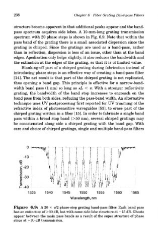
238                            Chapter 6 Fiber Grating Band-pass Filters

         structure become apparent in that additional peaks appear and the band-
         pass spectrum acquires side lobes. A 10-mm-long grating transmission
         spectrum with 20 phase steps is shown in Fig. 6.9. Note that within the
         pass band of the grating there is a small associated dispersion since the
         grating is chirped. Since the gratings are used as a band-pass, rather
         than in reflection, dispersion is less of an issue, other than at the band
         edges. Apodization only helps slightly; it also reduces the bandwidth and
        the extinction at the edges of the grating, so that it is of limited value.
             Blanking-off part of a chirped grating during fabrication instead of
        introducing phase steps is an effective way of creating a band-pass filter
         [14]. The net result is that part of the chirped grating is not replicated,
        thus opening a band gap. This principle is effective for a narrow-band-
        width band pass (1 nm) so long as /cL < TT. With a stronger reflectivity
         grating, the bandwidth of the band stop increases to encroach on the
        band pass from both sides, reducing the pass-band width. An alternative
        technique uses UV postprocessing first reported for UV trimming of the
        refractive index of photosensitive waveguides [53], to erase part of the
         chirped grating written in a fiber [15]. In order to fabricate a single band
        pass within a broad stop band (>50 nm), several chirped gratings may
        be concatenated along side a chirped grating with the band gap. With
         care and choice of chirped gratings, single and multiple band-pass filters


        Figure 6.9: A 20 x ?7/2 phase-step grating band-pass filter. Each band pass
        has an extinction of >30 dB, but with some side-lobe structure at —15 dB. Ghosts
         appear between the main pass bands as a result of the super structure of phase
         steps at —30 dB transmission.