
Page 260 - Fiber Bragg Gratings
P. 260
6.1 Distributed feedback, Fabry-Perot, superstructure, and moire gratings 237
While the principle of multiple phase shift within a single grating is
useful, it has the additional effect of increasing the side-lobe structure
despite apodization. The side lobes increase as a result of the formation
of a super structure (see Chapter 3) and is discussed in the next section.
Other methods need to be used to position the band pass and for a broader-
bandwidth band pass and more controllable bandwidth of the band stop.
A simple technique to accurately create a band pass at a particular
wavelength is to introduce a phase step within a chirped grating. A start
and a stop Bragg wavelength characterize a chirped grating. In a linearly
chirped grating, the position of the local Bragg wavelength is uniquely
known. Placing a 77/2 phase step at that point results in a band pass at
the local Bragg wavelength.
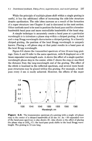
Figure 6.8 shows the transmitted spectrum of two 10-mm-long grat-
ings. Data A and B refer to the same spectrum, with B displayed on a 30
times expanded wavelength scale. A shows the effect of a single quarter-
wavelength phase step in the center, while C shows the step at one-third
the distance from the long-wavelength end of the grating. The effect of
the stitch is localized in the reflected spectrum, and several more band-
pass structures may be placed within this grating. For example, a band-
pass every 2 nm is easily achieved. However, the effects of the super
Figure 6.8: The transmission spectrum of a grating with a single 77/2 phase
step in the center of a chirped bandwidth of 20 nm (A). An X30 expanded view
of the band-pass spectrum is also shown (B). Also shown is the effect of placing
the phase step at 2/3L g (C); the band-pass peak shifts to the local Bragg wave-
length. The grating is 10 mm long.