
Page 292 - Fiber Bragg Gratings
P. 292
6.5 The optical circulator based OADM 269
edges of the reflection band (see Chapter 4). If the signal fills the grating
or is severely limited by the grating bandwidth, apart from the simple
pulse broadening (narrowed spectrum), additional dispersion from the
band edges of the grating has the potential of causing severe pulse distor-
tion. This area has only recently received attention [631.
Programmability of an OADM is often desirable, and there are several
techniques available to integrate this feature. As has been seen with
the GMZI-BPF, the most easily adjustable parameter is the path length
difference from the coupler to the gratings, since tuning the Bragg wave-
length of both gratings poses a difficult engineering problem. The OC-
ADM is not an interferometric device, so that tuning of the gratings by
stretching/compressing or heating is easily achieved. Quetel et al. [651
demonstrated this principle with a circulator and four gratings stretch
tuned by piezoelectric (PZT) actuators, with a switching time of 40 ytts
and a voltage of only 50 V. Okayama et al. [64] proposed the use of a pair
of identical gratings for each add/drop channel with two 4-port optical
circulators for an OC-based tunable add-drop multiplexer (OC-TADM).
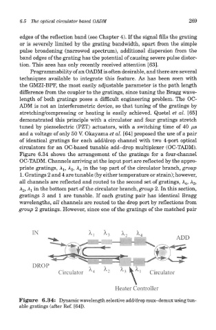
Figure 6.34 shows the arrangement of the gratings for a four-channel
OC-TADM. Channels arriving at the input port are reflected by the appro-
priate gratings, A 1? A 2, A 4 in the top part of the circulator branch, group
1. Gratings 2 and 4 are tunable (by either temperature or strain); however,
all channels are reflected and routed to the second set of gratings, A 4, A 2,
A 2, Aj in the bottom part of the circulator branch, group 2. In this section,
gratings 3 and 1 are tunable. If each grating pair has identical Bragg
wavelengths, all channels are routed to the drop port by reflections from
group 2 gratings. However, since one of the gratings of the matched pair
Figure 6.34: Dynamic wavelength selective add/drop mux-demux using tun-
able gratings (after Ref. [64]).