
Page 295 - Fiber Bragg Gratings
P. 295
272 Chapter 6 Fiber Grating Band-pass Filters
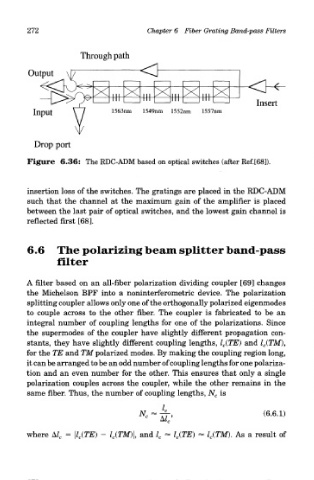
Figure 6.36: The RDC-ADM based on optical switches (after Ref.[68]).
insertion loss of the switches. The gratings are placed in the RDC-ADM
such that the channel at the maximum gain of the amplifier is placed
between the last pair of optical switches, and the lowest gain channel is
reflected first [68].
6.6 The polarizing beam splitter band-pass
filter
A filter based on an all-fiber polarization dividing coupler [69] changes
the Michelson BPF into a noninterferometric device. The polarization
splitting coupler allows only one of the orthogonally polarized eigenmodes
to couple across to the other fiber. The coupler is fabricated to be an
integral number of coupling lengths for one of the polarizations. Since
the supermodes of the coupler have slightly different propagation con-
stants, they have slightly different coupling lengths, l c(TE) and l c(TM),
for the TE and TM polarized modes. By making the coupling region long,
it can be arranged to be an odd number of coupling lengths for one polariza-
tion and an even number for the other. This ensures that only a single
polarization couples across the coupler, while the other remains in the
same fiber. Thus, the number of coupling lengths, N c is
where A/ c - \l c(TE) - l c(TM)\, and l c ~ l c(TE) « l c(TM). As a result of