
Page 298 - Fiber Bragg Gratings
P. 298
6.6 The polarizing beam splitter band-pass filter 275
PDBPF, 0.47-ps pulses at 1562 nm were stretched to 60 ps after propaga-
tion through 0.55 km of partially dispersion-shifted fiber (dispersion of 9
ps/nm). A pair of identical 8-mm-long chirped gratings with a bandwidth
of 12 nm in the PDBPF routed the pulses to a second, identical DCG-
PBS-BPF. The output port of the second PBS-BPF recovered pulses of
0.50 ps, a recompression ratio of 60/0.5 = 109 [721.
The PBS-BPF is a noninterferometric device but relies on the coinci-
dence of the arrival of the pulses at the PDS after reflection. A delay between
the arrival of the pulses translates into polarization mode dispersion
(PMD). A change in the path of 1 mm is equivalent to ~ 10 ps PMD. For such
short pulses, the paths were matched to <0.01 mm by stretching the fiber.
Polarization variation in each arm causes an amplitude fluctuation. This
device remains reasonably immune from physical disturbance, so long as
the fibers after the PBS are not disturbed. Since all the components of this
device are based on optical fiber, it has low insertion loss (—0.2 dB, typically,
for the splitter).
The Michelson interferometer becomes the GMZI-ADM when a second
coupler is included after the gratings. The same applies to the polarization
dividing filter with a second PBS after the gratings. However, a major differ-
ence is the intrinsic stability of the latter device, since interferometer stabil-
ity is no longer necessary. BER performance of transmission systems will
degrade significantly as the PMD approaches half of the bit period. For a
low BER at a transmission rate of 10 Gb/sec, a maximum path imbalance
of a few millimeters would be required, which is easily achievable. The dis-
advantage of the filter is relatively small bandwidth of the PBS (see Fig.
6.36), so that channels can only be spaced close to the nulls of the PBS.
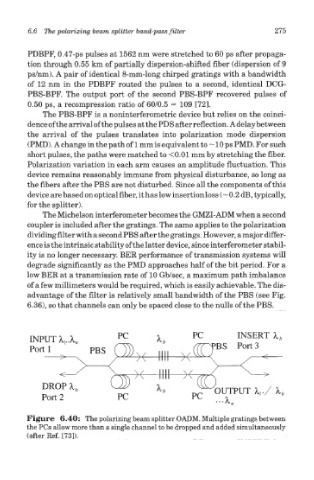
Figure 6.40: The polarizing beam splitter OADM. Multiple gratings between
the PCs allow more than a single channel to be dropped and added simultaneously
(after Ref. [73]).