
Page 303 - Fiber Bragg Gratings
P. 303
280 Chapter 6 Fiber Grating Band-pass Filters
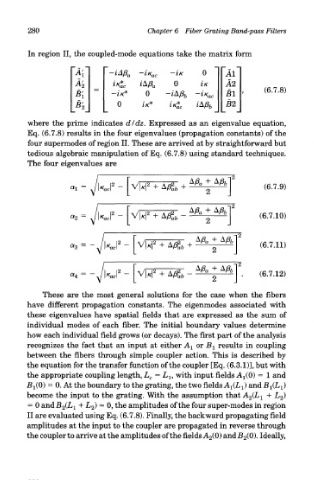
In region II, the coupled-mode equations take the matrix form
where the prime indicates dldz. Expressed as an eigenvalue equation,
Eq. (6.7.8) results in the four eigenvalues (propagation constants) of the
four supermodes of region II. These are arrived at by straightforward but
tedious algebraic manipulation of Eq. (6.7.8) using standard techniques.
The four eigenvalues are
These are the most general solutions for the case when the fibers
have different propagation constants. The eigenmodes associated with
these eigenvalues have spatial fields that are expressed as the sum of
individual modes of each fiber. The initial boundary values determine
how each individual field grows (or decays). The first part of the analysis
recognizes the fact that an input at either A 1 or B l results in coupling
between the fibers through simple coupler action. This is described by
the equation for the transfer function of the coupler [Eq. (6.3.1)], but with
the appropriate coupling length, L c = L l9 with input fields Aj/O) = 1 and
B^O) = 0. At the boundary to the grating, the two fields A-^L-^) and B^L-^
become the input to the grating. With the assumption that A 2(L l + L 2)
=
= 0 and-B 2Cki + ^2) 0> the amplitudes of the four super-modes in region
II are evaluated using Eq. (6.7.8). Finally, the backward propagating field
amplitudes at the input to the coupler are propagated in reverse through
the coupler to arrive at the amplitudes of the fields A 2(0) and B 2(0). Ideally,