
Page 311 - Fiber Bragg Gratings
P. 311
288 Chapter 6 Fiber Grating Band-pass Filters
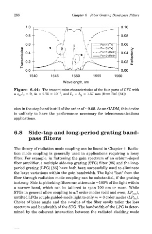
Figure 6.44: The transmission characteristics of the four ports of GFC with
3
a K ac L c = 9, 8n = 2.75 X 1(T , and L c - L g = 1.57 mm (from Ref. [84]).
sion in the stop band is still of the order of—0.05. As an OADM, this device
is unlikely to have the performance necessary for telecommunications
applications.
6.8 Side-tap and long-period grating band-
pass filters
The theory of radiation mode coupling can be found in Chapter 4. Radia-
tion mode coupling is generally used in applications requiring a lossy
filter. For example, in flattening the gain spectrum of an erbium-doped
fiber amplifier, a multiple side-tap grating (STG) filter [85] and the long-
period grating (LPG) [86] have both been successfully used to eliminate
the large variations within the gain bandwidth. The light "lost" from the
fiber through radiation mode coupling can be substantial, if the grating
is strong. Side-tap blocking filters can attenuate ~ 100% of the light within
a narrow band, which can be tailored to span 100 nm or more. While
STGs in general allow coupling to all order modes (odd and even, LP mn),
untilted LPGs couple guided-mode light to only m — 0 order modes (LP 0n).
Choice of blaze angle and the u-value of the fiber easily tailor the loss
spectrum and bandwidth of the STG. The bandwidth of the LPG is deter-
mined by the coherent interaction between the radiated cladding mode