
Page 319 - Fiber Bragg Gratings
P. 319
296 Chapter 6 Fiber Grating Band-pass Filters
filter is shown in Fig. 6.51. The transmitted output intensity can be shown
to be [106]
where k = 2 id A., L r is the length of the rocking filter, L s is the distance
between the two filters, /c ac = An/A n and B is the birefringence, n x — n y The
detuning parameter A/3 = /3 X — /3 y — 2 TT/A, with the usual definition of a (see
Chapter 4). If the filter separation L s <L cohL b/A, where L coh is the coherence
length of the source, then strong interference is visible at the output.
Kannellopoulos et al. [106] fabricated the filter in Andrew Corp D-fiber
with a polarization beat length of 4.35 mm (L b) at a wavelength of 780 nm
4
and B — n x — n y = 1.8 X 10~ . The core-to-cladding index difference was
2
3.3 X 10~ with ahigher mode cutoff of 710 nm. The rocking filters centered
at 787 nm were 224.4 mm long (L r) and separated by 320 mm (L s). The period
of the gratings was 4.4 mm, and they were written with 266-nm wavelength
2
pulsed radiation, exposed to 2400 pulses at a peak intensity of 1.4 MW/cm .
Each filter had a coupling efficiency of 7.5% so that the peak refractive index
7
modulation <5A/i' = 9.7xlO~ . Figure 6.52 shows the transmission charac-
teristics of the polarization coupling MZI. The output shows three peaks
in transmission, each with a FW bandwidth of ~8 nm. The temperature
sensitivity of the resonant wavelength of the filter is high (0.5 nm/°C) com-
pared to that of Bragg gratings (0.006 nm/°C), and so the filter is suited to
sensing temperature. When one of the filters is heated, the resonant wave-
length shifts; alternatively, heating the section between the couplers influ-
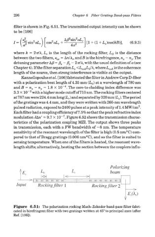
Figure 6.51: The polarization rocking Mach-Zehnder band-pass filter fabri-
cated in birefringent fiber with two gratings written at 45° to principal axes (after
Ref. [106]).