
Page 346 - Fiber Bragg Gratings
P. 346
7.2 Chirped and step-chirped gratings 323
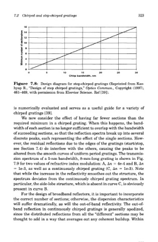
Figure 7.8: Design diagram for step-chirped gratings (Reprinted from Kas-
hyap R., "Design of step chirped gratings," Optics Commun., Copyright (1997),
461-469, with permission from Elsevier Science. Ref [39]).
is numerically evaluated and serves as a useful guide for a variety of
chirped gratings [39].
We now consider the effect of having far fewer sections than the
required minimum in a chirped grating. When this happens, the band-
width of each section is no longer sufficient to overlap with the bandwidth
of succeeding sections, so that the reflection spectra break up into several
discrete peaks, each representing the effect of the single sections. How-
ever, the residual reflections due to the edges of the gratings (start/stop,
see Section 7.4) do interfere with the others, causing the peaks to be
altered from the smooth curves of uniform period gratings. The transmis-
sion spectrum of a 5-nm bandwidth, 8-mm-long grating is shown in Fig.
7.9 for two values of refractive index modulation: A, A/I = 4e-4 and B, An
= le-3, as well as a continuously chirped grating (C, An = le-3). Note
that while the increase in the reflectivity smoothes out the structure, the
spectrum deviates from the continuously chirped grating spectrum. In
particular, the side-lobe structure, which is absent in curve C, is obviously
present in curve B.
For the design of broadband reflectors, it is important to incorporate
the correct number of sections; otherwise, the dispersion characteristics
will suffer dramatically, as will the out-of-band reflectivity. The out-of-
band reflection in continuously chirped gratings is generally apodized,
since the distributed reflections from all the "different" sections may be
thought to add in a way that averages out any coherent buildup. Within