
Page 362 - Fiber Bragg Gratings
P. 362
7.5 Systems measurements with DCGs 339
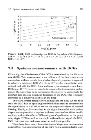
Figure 7.23: PMD vs dispersion in a DCG for five values of birefringence,
5
6
7
8
A (B = 1 x 1(T ), B (B = I X 1(T ), C (5 = 1 x 1(T ), D (B = I x 1(T ), and
4
E (B = 1 X 10~ ).
7.5 Systems measurements with DCGs
Ultimately, the effectiveness of the DCG is determined by the bit error
rate (BER). This measurement is an indicator of the how many errors
are received within a certain time window. Generally, a system is expected
9
to achieve a minimum BER of 1 bit in 10~ at the transmission rate,
without and with the DCG. Some undersea systems require even lower
15
BERs (e.g., 10~ ). However, in order to compare the transmission perfor-
mance, the power has to be increased at the receiver to compensate for
insertion loss and any nonlinear dispersion in the DCG. This is usually
expressed as a penalty in decibels at the BER.
There are several parameters that influence the BER. As has been
seen, the DCG has an operating bandwidth that needs to accommodate
the signal down to —20 dB, to reduce the dispersive effects of spectral
filtering. Ideally, a filter matched to the signal bandwidth with perfect
dispersion compensation is required with zero insertion loss. Other consid-
erations, such as the effect of different types of apodization on the group
delay ripple (GDR) as well as the ripple in the reflected signal of a DCG,
PMD, insertion loss, and so on, cause an additional penalty.
There have been many demonstrations of dispersion compensation
using DCGs: from compensation of the chirp from a semiconductor laser