
Page 364 - Fiber Bragg Gratings
P. 364
7.5 Systems measurements with DCGs 341
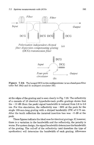
Figure 7.24: The lumped DCG in two configurations: (a) as a band-pass filter
(after Ref. [64]) and (b) multiport circulator [65].
at the edges of the grating and is seen clearly in Fig. 7.25. The reflectivity
of a cascade of 10 identical hyperbolic-tanh profile gratings shows that
the -10 dB (from the peak) signal bandwidth is reduced from 0.8 to 0.6
nm. For this simulation, the reflectivity was —90% at the peak for the
single 100-mm-long grating with a chirped bandwidth (FW) of 0.75 nm.
After the tenth reflection the incurred insertion loss was ~5 dB at the
peak.
These figures indicate the ideal case for identical gratings. If, however,
there is a variation in the bandwidth and the reflectivity, the penalty is
worse. For system design, the signal bandwidth determines the bandwidth
of the grating. The roll-off of the reflectivity (and therefore the type of
apodization) will determine the bandwidth of each grating. Allowance