
Page 106 - Finite Element Analysis with ANSYS Workbench
P. 106
5.4 Application 97
The next step is to impose the boundary condition of
fixed support along rims of the three holes. On the upper
surface, we impose the boundary condition of the frictionless
support with the vertical load of 100 N. These imposed
boundary conditions are shown in the figure.
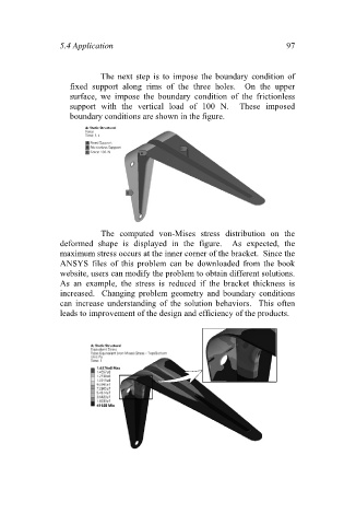
The computed von-Mises stress distribution on the
deformed shape is displayed in the figure. As expected, the
maximum stress occurs at the inner corner of the bracket. Since the
ANSYS files of this problem can be downloaded from the book
website, users can modify the problem to obtain different solutions.
As an example, the stress is reduced if the bracket thickness is
increased. Changing problem geometry and boundary conditions
can increase understanding of the solution behaviors. This often
leads to improvement of the design and efficiency of the products.