
Page 172 - Finite Element Analysis with ANSYS Workbench
P. 172
8.2 Fatigue and Life Prediction 163
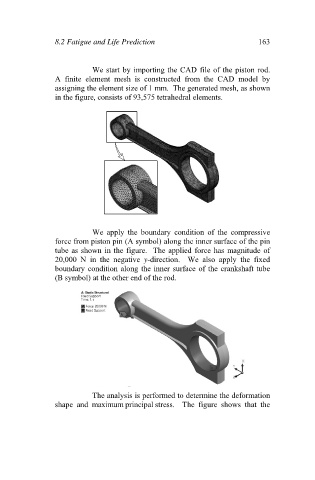
We start by importing the CAD file of the piston rod.
A finite element mesh is constructed from the CAD model by
assigning the element size of 1 mm. The generated mesh, as shown
in the figure, consists of 93,575 tetrahedral elements.
We apply the boundary condition of the compressive
force from piston pin (A symbol) along the inner surface of the pin
tube as shown in the figure. The applied force has magnitude of
20,000 N in the negative y-direction. We also apply the fixed
boundary condition along the inner surface of the crankshaft tube
(B symbol) at the other end of the rod.
The analysis is performed to determine the deformation
shape and maximum principal stress. The figure shows that the