
Page 236 - Finite Element Analysis with ANSYS Workbench
P. 236
11.4 Application 227
11.4 Application
11.4.1 Flow in Piping System
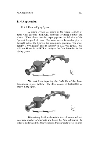
A piping system as shown in the figure consists of
pipes with different diameters, reservoir, reducing adapter and
elbow. Water flows into the larger pipe on the left side of the
figure at the speed of 1 m/s. The water leaves the smaller pipe on
the right side of the figure at the atmospheric pressure. The water
3
density is 998.2 kg/m and its viscosity is 0.001003 kg/m-s. We
will use Fluent in ANSYS to analyze the flow behavior in this
piping system.
We start from importing the CAD file of the three-
dimensional piping system. The flow domain is highlighted as
shown in the figure.
Discretizing the flow domain in three dimensions leads
to a large number of elements and hence the flow unknowns. In
order to understand the flow behavior, this particular problem may