
Page 171 - Finite Element Modeling and Simulations with ANSYS Workbench
P. 171
156 Finite Element Modeling and Simulation with ANSYS Workbench
3. Apply the load and constraints to the FE model correctly.
4. Conduct 2-D stress analysis of an FE model using ANSYS Workbench.
PROBLEMS
4.1 List the boundary conditions in Example 4.1.
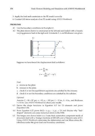
4.2 The plate shown below is constrained at the left end and loaded with a linearly
varying pressure load at the right end. Constants E, ν, and thickness t are given.
y
p o
h
x
h
L
Suppose we have found the displacement field as follows:
u = p 0 xy,
Eh
v =− p 0 ( x + ν y )
2
2
2 Eh
Find:
a. strains in the plate;
b. stresses in the plate;
c. check if or not the equilibrium equations are satisfied by the stresses;
d. check if or not the boundary conditions are satisfied by the solution.
Optional:
Assume E = 10 × 10 psi, ν = 0.3, p = 100 psi, L = 12 in., h = 4 in., and thickness
6
o
t = 0.1 in. Use ANSYS Workbench to check your results.
4.3 Derive the shape functions in Equation 4.17 for T3 elements and prove
(Equation 4.18).
2
23
4.4 From Equation 4.27, prove det J = xy 23 − xy 13 = A and discuss why “bad-
13
shaped” elements can cause numerical errors in the FEM.
4.5 The torque arm shown below is a 5 mm thick automotive component made of
structural steel with a Young’s modulus of 200 GPa and a Poisson’s ratio of 0.3.
Using ANSYS Workbench, determine the deformation and von Mises stress dis-
tributions under the given load and boundary conditions.