
Page 221 - Finite Element Modeling and Simulations with ANSYS Workbench
P. 221
206 Finite Element Modeling and Simulation with ANSYS Workbench
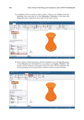
Two Surfaces will be created as shown below. Click on one Surface from the
Structure Tree, and enter 4 for the Midsurface Thickness in the lower left
Properties panel. Repeat the same steps for the other surface.
To check surface normal directions, click the Normal icon in the Quality group
on the Measure tab. Ctrl-click the two surfaces in Graphics Window. The
surface normal direction at the point where you click will be displayed. The
inward pointing arrows shown below indicate incorrect surface normals.