
Page 225 - Finite Element Modeling and Simulations with ANSYS Workbench
P. 225
210 Finite Element Modeling and Simulation with ANSYS Workbench
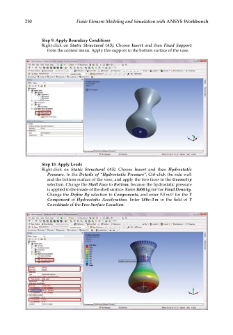
Step 9: Apply Boundary Conditions
Right-click on Static Structural (A5). Choose Insert and then Fixed Support
from the context menu. Apply this support to the bottom surface of the vase.
Step 10: Apply Loads
Right-click on Static Structural (A5). Choose Insert and then Hydrostatic
Pressure. In the Details of “Hydrostatic Pressure”, Ctrl-click the side wall
and the bottom surface of the vase, and apply the two faces to the Geometry
selection. Change the Shell Face to Bottom, because the hydrostatic pressure
3
is applied to the inside of the shell surface. Enter 1000 kg/m for Fluid Density.
2
Change the Define By selection to Components, and enter 9.8 m/s for the Y
Component of Hydrostatic Acceleration. Enter 180e-3 m in the field of Y
Coordinate of the Free Surface Location.