
Page 230 - Finite Element Modeling and Simulations with ANSYS Workbench
P. 230
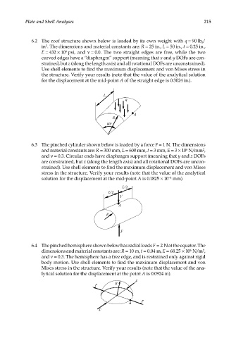
Plate and Shell Analyses                                                    215


               6.2  The roof structure shown below is loaded by its own weight with q = 90 lb /
                                                                                       f
                   in . The dimensions and material constants are: R = 25 in., L = 50 in., t = 0.25 in.,
                     2
                   E = 432 × 10  psi,  and  ν = 0.0. The two straight edges are free, while the two
                             6
                   curved edges have a “diaphragm” support (meaning that x and y DOFs are con-
                   strained, but z (along the length axis) and all rotational DOFs are unconstrained).
                   Use shell elements to find the maximum displacement and von Mises stress in
                   the structure. Verify your results (note that the value of the analytical solution
                   for the displacement at the mid-point A of the straight edge is 0.3024 in.).


                                             L
                                                      q


                                                          A
                                                 R
                                               80°


               6.3  The pinched cylinder shown below is loaded by a force F = 1 N. The dimensions
                   and material constants are: R = 300 mm, L = 600 mm, t = 3 mm, E = 3 × 10  N/mm ,
                                                                                       2
                                                                                6
                   and ν = 0.3. Circular ends have diaphragm support (meaning that y and z DOFs
                   are constrained, but x (along the length axis) and all rotational DOFs are uncon-
                   strained). Use shell elements to find the maximum displacement and von Mises
                   stress in the structure. Verify your results (note that the value of the analytical
                   solution for the displacement at the mid-point A is 0.1825 × 10  mm).
                                                                         −4
                                                     L/2
                                               L/2
                                                    F
                                                    A
                                              R


                                                    F


               6.4  The pinched hemisphere shown below has radial loads F = 2 N at the equator. The
                                                                                  6
                   dimensions and material constants are: R = 10 m, t = 0.04 m, E = 68.25 × 10  N/m ,
                                                                                       2
                   and ν = 0.3. The hemisphere has a free edge, and is restrained only against rigid
                   body motion. Use shell elements to find the maximum displacement and von
                   Mises stress in the structure. Verify your results (note that the value of the ana-
                   lytical solution for the displacement at the point A is 0.0924 m).
                                                           F
                                          F       R


                                                        A    F
                                           F