
Page 227 - Finite Element Modeling and Simulations with ANSYS Workbench
P. 227
212 Finite Element Modeling and Simulation with ANSYS Workbench
Modeling tips: Surface bodies can be created from planar 2D sketches, or by revolv-
ing, extruding or sweeping lines or curves. In many case, they can also be cre-
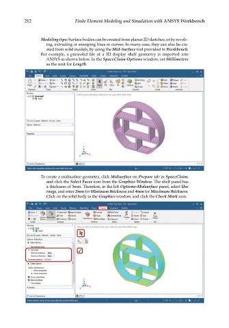
ated from solid models, by using the Mid-Surface tool provided in Workbench.
For example, a parasolid file of a 3D display shelf geometry is imported into
ANSYS as shown below. In the SpaceClaim Options window, set Millimeters
as the unit for Length.
To create a midsurface geometry, click Midsurface on Prepare tab in SpaceClaim,
and click the Select Faces icon from the Graphics Window. The shelf panel has
a thickness of 3mm. Therefore, in the left Options-Midsurface panel, select Use
range, and enter 2mm for Minimum thickness and 4mm for Maximum thickness.
Click on the solid body in the Graphics window, and click the Check Mark icon.