
Page 375 - Finite Element Modeling and Simulations with ANSYS Workbench
P. 375
360 Finite Element Modeling and Simulation with ANSYS Workbench
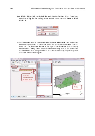
Add Wall – Right-click on Default Domain in the Outline. Select Insert and
then Boundary. In the pop-up menu shown below, set the Name to Wall.
Click Ok.
In the Details of Wall in Default Domain in Flow Analysis 1, click on the but-
ton to the right of the Location field under the tab of Basic Settings. To select
faces, click the Selection Button to the right of the Location field to display
the Selection Dialog Panel. Ctrl-click the remaining faces in the panel until
all the desired faces (the ground and truck surfaces) are highlighted in green,
and click Ok to close the panel.