
Page 392 - Finite Element Modeling and Simulations with ANSYS Workbench
P. 392
Design Optimization 377
x 3
x 2
x 1
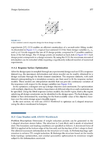
FIGURE 11.5
A face-centered central composite design for three design variables.
experiments [17]. CCD enables an efficient construction of a second-order fitting model.
As illustrated in Figure 11.5, a typical face-centered CCD for three design variables (x , x ,
2
1
and x ) at 3 levels suggests the use of 15 design points, compared to 3 possible combina-
3
3
tions of the full design. The 15 design points are marked as back dots in Figure 11.5. Each
design point corresponds to a design scenario. By using the CCD, the maximum amount of
information can be extracted while requiring a significantly reduced number of numerical
experiments.
11.4.2 Response Surface Optimization
After the design space is sampled through an experimental design such as CCD, a response
dataset (e.g., the maximum deformation and stress results) can be readily obtained for a
design scenario through the finite element simulation. The response datasets, with each
dataset corresponding to a simulation scenario, are then used to fit the response surface
models. These models are interpolation models that can provide continuous variation of
the responses with respect to the design variables (see Figure 11.4).
In the optimizer, a designer sets up a design objective and constraints. For optimization
with multiple objectives, the relative importance of different objectives and constraints can
be specified. Using the fitted response surface models, the feasible region, that is, the region
satisfying all design constraints can be identified in the design space. The best design can-
didate is then determined by searching for the best available value of the objective func-
tion over the entire design space’s feasible region.
In the next section, we will use ANSYS Workbench to optimize an L-shaped structure
using the above-mentioned techniques.
11.5 Case Studies with ANSYS Workbench
Problem Description: Determine if weight reduction pockets can be generated in the
L-shaped structure shown below. The structure is 2 mm thick and is made of structural
steel. The boundary and loading conditions are specified as follows: A downward force of
300 N is applied at the bottom edge of the free end, and the top face of the L-shape is fixed.
The allowed maximum deformation in the structure is 0.3 mm. A) Perform topology opti-
mization to achieve 75% weight reduction. B) Redesign the structure based on the results
from topology optimization, and conduct parametric optimization to minimize weight
subject to the deformation constraint.