
Page 168 - Flexible Robotics in Medicine
P. 168
154 Chapter 6
It can be seen from the three devices that the linear actuation is usually placed behind or
offset, while the rotary actuation is carried on the linear track. In addition, both the linear
track and rotation axis have measurement guides to facilitate accurate position tracking.
Accurate position measurements allow for the use of inverse kinematics to control the shape
of the robot accurately. However, as noted by the authors of the autoclavable steerable
cannula, the movement of the cannula has to be input in a step-by-step sequence. As such,
they recommend using a manual actuation method without many dynamically manipulated
tubes [2]. The authors further noted that the use of gears resulted in problems with
backlash.
6.2.2 Motor actuated
CTR actuation, or more broadly, steerable needle actuation, can be motor actuated. Motor
actuated systems are superior to manually actuated ones, as the inverse kinematic mapping
can be done in real-time by a computer, as well as the execution. This further opens new
possibilities for surgery, such as teleoperation and surgery, using imaging techniques such
as magnetic resonance imaging (MRI).
One such device is an MRI-guided CTR like the manually actuated CTRs [21], using a
modular design, with each tube sitting on a linear guide. Similar actuation design
principles can additionally be noted, where the translation is offset from the tube axis.
However, this CTR uses pulley systems for translation and rotation. This helped to address
the issues of backlash that could occur from using gears. For the translation axis,
actuation was not done by rotating the lead screw, but instead by using a pulley to turn
the nut. This device is modular, as both translation and rotation are housed in the same
unit [21].
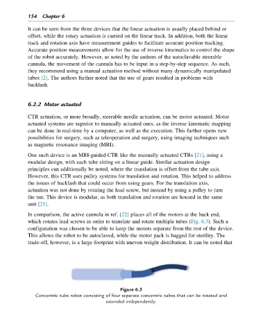
In comparison, the active cannula in ref. [22] places all of the motors at the back end,
which rotates lead screws in order to translate and rotate multiple tubes (Fig. 6.3). Such a
configuration was chosen to be able to keep the motors separate from the rest of the device.
This allows the robot to be autoclaved, while the motor pack is bagged for sterility. The
trade-off, however, is a large footprint with uneven weight distribution. It can be noted that
Figure 6.3
Concentric tube robot consisting of four separate concentric tubes that can be rotated and
extended independently.