
Page 190 - Flexible Robotics in Medicine
P. 190
Tendon routing and anchoring for cableriven single-t surgical manipulators 177
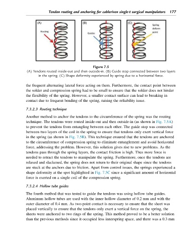
Figure 7.5
(A) Tendons routed inside-out and then outside-in. (B) Guide stop connected between two layers
in the spring. (C) Shape deformity experienced by spring due to a horizontal force.
the frequent alternating lateral force acting on them. Furthermore, the contact point between
the solder and compression spring had to be small to ensure that the solder does not hinder
the flexibility of the spring. However, a smaller contact surface can lead to breaking in
contact due to frequent bending of the spring, raising the reliability issue.
7.3.2.3 Routing technique
Another method to anchor the tendons to the circumference of the spring was the routing
technique. The tendons were routed inside-out and then outside-in (as shown in Fig. 7.5A)
to prevent the tendons from entangling between each other. The guide stop was connected
between two layers of the coil in the spring to ensure that tendons only exert vertical force
in the spring (as shown in Fig. 7.5B). This technique ensured that the tendons are anchored
to the circumference of compression spring to eliminate entanglement and avoid horizontal
force, addressing the problem. However, this solution gives rise to new problems. As the
tendons pass through the spring layers, the contact friction is high. Thus more force is
needed to retract the tendons to manipulate the spring. Furthermore, once the tendons are
relaxed and slackened, the spring does not return to their original shape since the tendons
are stuck at the anchors due to friction. Apart from control issues, the springs experienced a
shape deformity at the spot highlighted in Fig. 7.5C since a significant amount of horizontal
force is exerted on a single coil of the compression spring.
7.3.2.4 Hollow tube guides
The fourth method that was tested to guide the tendons was using hollow tube guides.
Aluminum hollow tubes are used with the inner hollow diameter of 0.2 mm and with the
outer diameter of 0.4 mm. As two-point contact is necessary to ensure that the sheet was
placed vertically to ensure that the tendons only exert a vertical force on the spring, the
sheets were anchored to two rings of the spring. This method proved to be a better solution
than the previous methods since it occupied less innerspring space, and there was a 0.3 mm