
Page 400 - Flexible Robotics in Medicine
P. 400
Single-port multichannel multi-degree-of-freedom robot 393
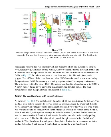
Figure 17.3
Detailed design of the robotic endoscopic system. (A) The arm of the manipulator in the initial
state. (B) The arm that formed as a triangulation during the operation. (C) The flexible wrist
joint. (D) The forceps. (E) The actuator.
endoscopic platform has two channels with the diameters of 2.8 and 3.8 mm for surgical
tools, respectively, a channel for the camera, and two channels for the air/water nozzle. The
diameter of each manipulator is 3.6 mm, with 6 DOFs. The distribution of the manipulator
DOFs in Fig. 17.2 includes three parts: a compliant arm, a flexible wrist joint, and a
gripper. The stiffness of the compliant arm with 2 DOFs can be tuned in real-time during
the operation to fulfill the accuracy and safety requirements of the surgery environment.
The wrist joint is flexible with 1 DOF. The gripper can bend in a broad range with 2 DOFs.
A screw motor based driver drives the manipulators via Bowden cables. The main
parameters of each manipulator are summarized in Table 17.1.
17.2.3 The compliant arm with variable stiffness
As shown in Fig. 17.3, five modules with diameters of 3.6 mm are designed for the arm. The
modules are a hollow structure to provide space for accommodating the wires with flexible
tubes. Semicircular surfaces connect the adjacent modules. Four wires (wire 1 to wire 4) and
two rods attached to the modules with flexible tubes are to drive the motion of the modules.
Wire 1 and wire 2, which passed through the holes in module 3, and the flexible tubes are
attached to the module 1. Module 1 and module 2 can be controlled to be bent by pulling
wire 1 and wire 2. The flexible tubes which passed through are attached to the holes of
module 4. Wire 3 and wire 4, which passed through the flexible tubes, are connected to the
module 3. Module 3 and module 4 can be bent by pulling the wire 3 and wire 4.