
Page 37 - Fluid Mechanics and Thermodynamics of Turbomachinery
P. 37
18 Fluid Mechanics, Thermodynamics of Turbomachinery
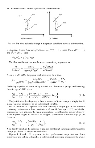
FIG. 1.9. The ideal adiabatic change in stagnation conditions across a turbomachine.
is obtained. Hence h 0s D C p T 01 [.p 02 /p 01 / .
1//
1]. Since C p D
R/.
1/
2
and a 01 D
RT 01 , then
h 0s /a 2 / f.p 02 /p 01 /.
01
The flow coefficient can now be more conveniently expressed as
p
P m P mRT 01 P m .RT 01 /
D p D p .
2
01 a 01 D 2 p 01 .
RT 01 /D 2 D p 01
2
As Pm 01 D .ND/, the power coefficient may be written
P P mC p T 0 C p T 0 T 0
O P D D D .
3
2
01 N D 5 f 01 D .ND/g.ND/ 2 .ND/ 2 T 01
Collecting together all these newly formed non-dimensional groups and inserting
them in eqn. (1.14b) gives
p
p 02 T 0 P m .RT 01 / ND
, , D f , p , Re,
. (1.15)
2
p 01 T 01 D p 01 .RT 01 /
The justification for dropping
from a number of these groups is simply that it
already appears separately as an independent variable.
For a machine of a specific size and handling a single gas it has become
customary, in industry at least, to delete
, R, and D from eqn. (1.15) and similar
expressions. If, in addition, the machine operates at high Reynolds numbers (or over
a small speed range), Re can also be dropped. Under these conditions eqn. (1.15)
becomes
p
p 02 T 0 P m T 01 N
, D f , p . (1.16)
p 01 T 01 p 01 T 01
Note that by omitting the diameter D and gas constant R, the independent variables
in eqn. (1.16) are no longer dimensionless.
Figures 1.10 and 1.11 represent typical performance maps obtained from
compressor and turbine test results. In both figures the pressure ratio across the whole