
Page 25 - Fluid Power Engineering
P. 25
2 Cha pte r O n e
hydraulic power was cheap, efficient, and easily transmitted through
300 km of underground cast-iron piping.
However, as electricity became cheaper and electronically pow-
ered equipment grew increasingly sophisticated, so industry and pri-
vate citizens began to abandon hydraulic power.
High-pressure fluid power systems were put into practical appli-
cation in 1925, when Harry Vickers developed the balanced vane
pump. Today, fluid power systems dominate most of the engineering
fields, partially or totally.
1.2 The Classification of Power Systems
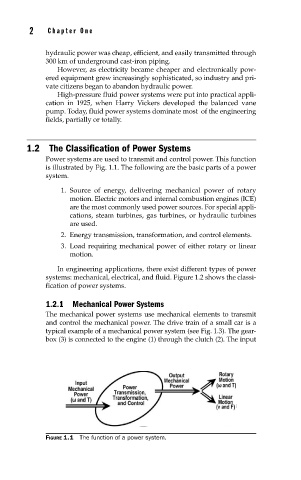
Power systems are used to transmit and control power. This function
is illustrated by Fig. 1.1. The following are the basic parts of a power
system.
1. Source of energy, delivering mechanical power of rotary
motion. Electric motors and internal combustion engines (ICE)
are the most commonly used power sources. For special appli-
cations, steam turbines, gas turbines, or hydraulic turbines
are used.
2. Energy transmission, transformation, and control elements.
3. Load requiring mechanical power of either rotary or linear
motion.
In engineering applications, there exist different types of power
systems: mechanical, electrical, and fluid. Figure 1.2 shows the classi-
fication of power systems.
1.2.1 Mechanical Power Systems
The mechanical power systems use mechanical elements to transmit
and control the mechanical power. The drive train of a small car is a
typical example of a mechanical power system (see Fig. 1.3). The gear-
box (3) is connected to the engine (1) through the clutch (2). The input
FIGURE 1.1 The function of a power system.