
Page 28 - Fluid Power Engineering
P. 28
Intr oduction to Hydraulic Power Systems 5
1.2.4 Hydrodynamic Power Systems
The hydraulic power systems transmit mechanical power by increas-
ing the energy of hydraulic liquids. Two types of hydraulic power
systems are used: hydrodynamic and hydrostatic.
Hydrodynamic (also called hydrokinetic) power systems transmit
power by increasing mainly the kinetic energy of liquid. Generally, these
systems include a rotodynamic pump, a turbine, and additional control
elements. The applications of hydrodynamic power systems are limited
to rotary motion. These systems replace the classical mechanical trans-
mission in the power stations and vehicles due to their high power-to-
weight ratio and better controllability.
There are two main types of hydrodynamic power systems:
hydraulic coupling and torque converter.
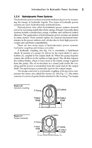
A hydraulic coupling (see Fig. 1.6) is essentially a fluid-based
clutch. It consists of a pump (2), driven by the input shaft (1), and a
turbine (3), coupled to the output shaft (4). When the pump impeller
rotates, the oil flows to the turbine at high speed. The oil then impacts
the turbine blades, where it loses most of the kinetic energy it gained
from the pump. The oil re-circulates in a closed path inside the cou-
pling and the power is transmitted from the input shaft to the output
shaft. The input torque is practically equal to the output torque.
The torque converter is a hydraulic coupling with one extra com-
ponent: the stator, also called the reactor (5). (See Fig. 1.7.) The stator
consists of a series of guide blades attached to the housing. The torque
FIGURE 1.6
Hydraulic coupling.
FIGURE 1.7
Torque converter.