
Page 316 - Fluid-Structure Interactions Slender Structure and Axial Flow (Volume 1)
P. 316
PIPES CONVEYING FLUID: NONLINEAR AND CHAOTIC DYNAMICS 297
f
i
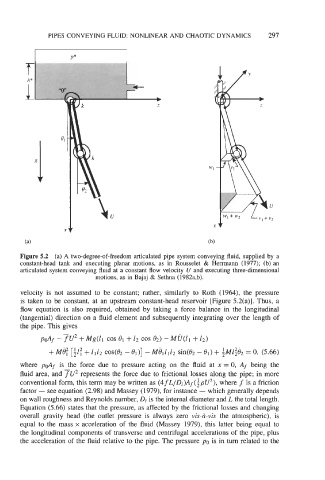
Figure 5.2 (a) A two-degree-of-freedom articulated pipe system conveying fluid, supplied by a
constant-head tank and executing planar motions, as in Rousselet & Henmann (1977); (b) an
articulated system conveying fluid at a constant flow velocity U and executing three-dimensional
motions, as in Bajaj & Sethna (1982a,b).
velocity is not assumed to be constant; rather, similarly to Roth (1964), the pressure
is taken to be constant, at an upstream constant-head reservoir [Figure 5.2(a)]. Thus, a
flow equation is also required, obtained by taking a force balance in the longitudinal
(tangential) direction on a fluid element and subsequently integrating over the length of
the pipe. This gives
+
pdf - Tu2 + Mg(zl COS el + z2 COS 0,) - MU(Z~ z2)
+Mi): [iZ: + Z1Z2 cos(Q2 - el)] - MB1Z1Z2 sin(& - 0,) + $14Zgb2 = 0, (5.66)
where pdf is the force due to pressure acting on the fluid at x = 0, Af being the
fluid area, and TU2 represents the force due to frictional losses along the pipe; in more
conventional form, this term may be written as (4fL/Di)Af(ipU2), where f is a friction
factor - see equation (2.98) and Massey (1979), for instance - which generally depends
on wall roughness and Reynolds number, Di is the internal diameter and L the total length.
Equation (5.66) states that the pressure, as affected by the frictional losses and changing
overall gravity head (the outlet pressure is always zero vis-&vis the atmospheric), is
equal to the mass x acceleration of the fluid (Massey 1979), this latter being equal to
the longitudinal components of transverse and centrifugal accelerations of the pipe, plus
the acceleration of the fluid relative to the pipe. The pressure po is in turn related to the