
Page 556 - Fluid-Structure Interactions Slender Structure and Axial Flow (Volume 1)
P. 556
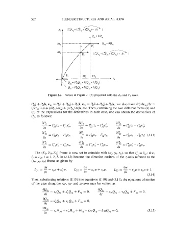
526               SLENDER STRUCTURES AND AXIAL FLOW


                              Figure 5.2  Forces in Figure J.l(b) projected onto the Zo and  YO axes.

                    1y2j + lF3k, ey0 = l;,i  + 1;2j + 1z3k, e,,  = l;,i  + 1T2j + 13*3k, we also have (b) ae,,/as  =
                    (aZ;,/as)i  + (aly,/as)j  + (i31f3/i3s)k, etc. Then, combining the two different forms (a) and
                    (b) of  the expressions for the derivatives in each case, one can obtain the derivatives of
                    l;j, as follows:


                      The (XO, YO, ZO) frame is now set to coincide with  (XO, yo, ZO), so that 17j = 6ij; also,
                    li = L3i, i = 1, 2, 3, in  (5.12) become the direction cosines of  the z-axis referred to  the
                    (xo, yo, LO) frame as given by
                           au                      av                      &   I
                                                                        =
                         = - - tov + K~W,    L32  = - - K,W  + sou,   ~33 - - K,U  + K,W  + 1.
                           as                      as                      as
                                                                                         (J. 14)
                    Then, substituting relations (5.13) into equations (5.10) and (J.l l), the equations of motion
                    of  the pipe along the xo-,  yo- and Lo-axes may be written as


                                                                                         (J. 15)