
Page 554 - Fluid-Structure Interactions Slender Structure and Axial Flow (Volume 1)
P. 554
524 SLENDER STRUCTURES AND AXIAL FLOW
The derivatives &,,/as, &,/as, aezo/as may be found by the same principle as those of
a rotating vector. Thus, &,,/as = S2 x e, = +,ezo + toeyo, where G? = Koe, + .;eyo +
toe,,; and similarly for the others. Then, using (J.l), one obtains
Combining equations (J.6)-(J.8) with (J.9), the components of the fluid acceleration
vector given in equations (6.15) may be obtained.
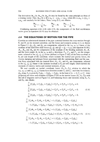
J.4 THE EQUATIONS OF MOTION FOR THE PIPE
Consider an infinitesimal element of the pipe contained between the cross-section through
PI and Pi on the strained centreline, and the forces and moments acting on it, as shown
in Figure J.l. Qxo, Qyo and Qzo are components, referred to the (x0, yo, zo) frame, of the
resultant of the transverse shear forces Q,, Qy and Q: = Q, +A,p, [see equation (6.18)];
Axe, hyo and A,, are the components of the resultant of the bending moments Ax, Ay
and the twist couple A, in the XO, yo and zo directions; F,, F, and F, are the compo-
nents, referred to the (& y& ,&) frame [defined in Figure J.l(b)] of the force resultant at
Pc per unit Iength of the centreline, which includes the inertial and gravity forces, the
viscous damping and pressure forces associated with the surrounding fluid and the reac-
tion force associated with the internal flow; Oxo, 0, and O,, are components, referred
to the (xb, y;, zb) frame of the moment resultant at Pt per unit length, which include the
moments of rotatory inertia and external moments, if any.
We next consider an inertial coordinate frame (XO, YO, ZO), relative to which the
(xo, yo, zo) and (x& y& 26) frames have direction cosines It and ZTj', such that, for instance,
Qyo along YO is given by lr2Qx0 + Eit2QyO + 1;2Qz0. In the limit of 6s -+ 0, l:j = It'. After
projecting all forces and moments in Figure J.l(b) on the inertial frame (XO, Yo, Zo) with
the aid of diagrams such as Figure 5.2, and balancing forces and moments along Xu, Yo
and ZO, one obtains
a
[ZTiQxo + l;iQyo + l;~Qzo] + lilFxo + E;lFyo + /;IFzo = 0,
a
- [GQxo + G2Qyo + l3*2Qzo] + 1;2Fq + l&Fyo + l3*2FZO = 0, (J. 10:
as
a
- ['?3QXo + '&QYO + %Qz0] + ly3Fxo + l;3Fy0 + 13*3Fz0 = 0,
as
a
-
as [l;i&xo + l&JGo + GiAzO] + 12 (173Q,W + Z&Qm + l&Q,>
- 13 (%Qq + l&.7Qy0 + Z&Q,) + (lyl@,, + Z$lOyo + I* 31 O ) = 0,
a
- [lLdh~ + G2Ayo +K&Azo] + 13 (l;lQxo + l;iQN + l;lQzo)
as
- '1 (';3 QxO + Z;3Qyo + Z3*3QZO) + (1;2@xo + 1z2Oyo + /3*2074) = 0, (J.11)
a
- [G'/uxg + 1$3 &yo + 13*3dzo] + !I (&Qq + l&QyO + l&Qz0)
as
- 12 (ZTiQxo + I&Qyo + l;lQQ) + (l;30x0 + Z&OyO + Z;30zo) 0,
=