
Page 176 - Fluid Catalytic Cracking Handbook
P. 176
Unit Monitoring and Control 149
3, Conversion of the flow rates to weight units (e.g., Ib/hr).
4, Normalization of the data to obtain a 100% weight balance.
5, Determination of the component yields.
6, Adjustment of the gasoline, LCO, and decanted oil yields to
standard cut points.
Input and Output Streams in the Overall Mass Balance
As shown in Envelope 1 of Figure 5-1, the input hydrocarbon
streams are fresh feed and coker off-gas. The output streams are FCC
tail gas (minus inerts), LPG, gasoline, LCO, DO, and coke.
Coke Yield Calculations
As discussed in Chapter 1, a portion of the feed is converted to coke
in the reactor. This coke is carried into the regenerator with the spent
catalyst. The combustion of the coke produces H 2O, CO, CO 2, SO 2,
and traces of NOx. To determine coke yield, the amount of dry air to
the regenerator and the analysis of flue gas are needed. It is essential
to have an accurate analysis of the flue gas. The hydrogen content of
coke relates to the amount of hydrocarbon vapors carried over with
the spent catalyst into the regenerator, and is an indication of the
reactor-stripper performance. Example 5-1 shows a step-by-step cal-
culation of the coke yield.
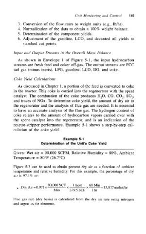
Example 5-1
Determination of the Unit's Coke Yield
Given: Wet air = 90,000 SCFM, Relative Humidity = 80%, Ambient
Temperature = 80°F (26.7°C)
Figure 5-3 can be used to obtain percent dry air as a function of ambient
temperature and relative humidity. For this example, the percentage of dry
air is 97.1% or:
n A- Ami 90,000SCF Imole 60 Min ,,,,.- , ,.
• Dry Air = 0.971 x — x x = 13,817 moles/hr
Min 379.5 SCF 1 hr
Flue gas rate (dry basis) is calculated from the dry air rate using nitrogen
and argon as tie elements.