
Page 170 - Fluid mechanics, heat transfer, and mass transfer
P. 170
148 PUMPS, EJECTORS, BLOWERS, AND COMPRESSORS
FIGURE 5.33 Steam jet ejector.
use of a smaller ejector, and a reduction in the amount & Figure 5.35 gives typical condensate drain leg
of steam required. layouts.
& Precondensers are used when the absolute pressure & Length of drain leg should be at least 10.33 m water
of the process is sufficiently high to allow conden- and 13.7 m for hydrocarbons.
sation at the temperature of the available water & Accumulation of trapped bubbles is a common haz-
supply. Noncondensables are removed from the pre- ard in barometric or shell and tube condenser
condenser by one or more ejector stages. tailpipes.
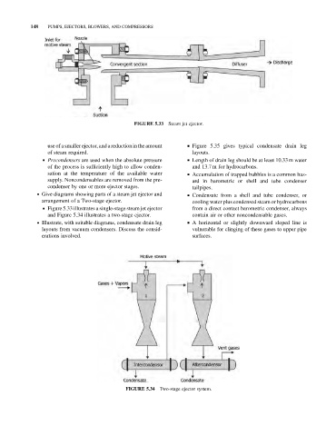
. Give diagrams showing parts of a steam jet ejector and & Condensate from a shell and tube condenser, or
arrangement of a Two-stage ejector. cooling water plus condensed steam or hydrocarbons
& Figure 5.33 illustrates a single-stage steam jet ejector from a direct contact barometric condenser, always
and Figure 5.34 illustrates a two-stage ejector. contain air or other noncondensable gases.
. Illustrate, with suitable diagrams, condensate drain leg & A horizontal or slightly downward sloped line is
layouts from vacuum condensers. Discuss the consid- vulnerable for clinging of these gases to upper pipe
erations involved. surfaces.
FIGURE 5.34 Two-stage ejector system.