
Page 362 - Fluid mechanics, heat transfer, and mass transfer
P. 362
HEAT TRANSFER EQUIPMENT INVOLVING PHASE TRANSFER
344
& There have been cases where the flooding led to
excessive liquid discharges from the column
overhead.
& Often this flooding occurs with formation of violent
slugs which uplift trays/packing and cause damage
with deformation and dislocation. Liquid levels ris-
ing above the reboiler return inlet is one of the most
common causes of this damage.
. What are the causes for the liquid levels rising above
reboiler return nozzle?
& Restriction in the bottoms outlet line, which includes
loss of bottoms pumping, obstruction by sediment
and debris and undersized outlet lines.
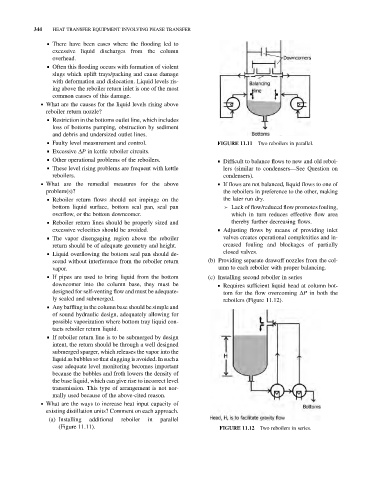
& Faulty level measurement and control. Two reboilers in parallel.
FIGURE 11.11
& Excessive DP in kettle reboiler circuits.
& Other operational problems of the reboilers. & Difficult to balance flows to new and old reboi-
& These level rising problems are frequent with kettle lers (similar to condensers—See Question on
reboilers. condensers).
. What are the remedial measures for the above & If flows are not balanced, liquid flows to one of
problem(s)? the reboilers in preference to the other, making
& Reboiler return flows should not impinge on the the later run dry.
bottom liquid surface, bottom seal pan, seal pan ➢ Lack of flow/reduced flow promotes fouling,
overflow, or the bottom downcomer. which in turn reduces effective flow area
& Reboiler return lines should be properly sized and thereby further decreasing flows.
excessive velocities should be avoided. & Adjusting flows by means of providing inlet
& The vapor disengaging region above the reboiler valves creates operational complexities and in-
return should be of adequate geometry and height. creased fouling and blockages of partially
& Liquid overflowing the bottom seal pan should de- closed valves.
scend without interference from the reboiler return (b) Providing separate drawoff nozzles from the col-
vapor. umn to each reboiler with proper balancing.
& If pipes are used to bring liquid from the bottom (c) Installing second reboiler in series
downcomer into the column base, they must be & Requires sufficient liquid head at column bot-
designed for self-venting flow and must be adequate- tom for the flow overcoming DP in both the
ly sealed and submerged. reboilers (Figure 11.12).
& Any baffling in the column base should be simple and
of sound hydraulic design, adequately allowing for
possible vaporization where bottom tray liquid con-
tacts reboiler return liquid.
& If reboiler return line is to be submerged by design
intent, the return should be through a well designed
submerged sparger, which releases the vapor into the
liquid as bubblesso that slugging is avoided. In such a
case adequate level monitoring becomes important
because the bubbles and froth lowers the density of
the base liquid, which can give rise to incorrect level
transmission. This type of arrangement is not nor-
mally used because of the above-cited reason.
. What are the ways to increase heat input capacity of
existing distillation units? Comment on each approach.
(a) Installing additional reboiler in parallel
(Figure 11.11). FIGURE 11.12 Two reboilers in series.