
Page 61 - Fluid mechanics, heat transfer, and mass transfer
P. 61
PIPING, SEALS, AND VALVES
38
& False.
. How would you estimate head losses for flow through
pipe fittings?
& Head losses are estimated empirically for various
fittings in terms of velocity head, using the equation,
2
h ¼ KV /2g, where K is the loss coefficient.
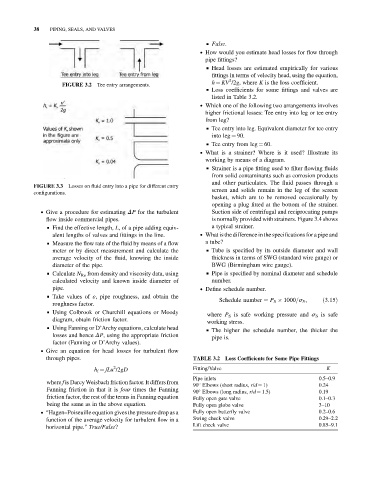
Tee entry arrangements.
FIGURE 3.2
& Loss coefficients for some fittings and valves are
listed in Table 3.2.
. Which one of the following two arrangements involves
higher frictional losses: Tee entry into leg or tee entry
from leg?
& Tee entry into leg. Equivalent diameter for tee entry
into leg ¼ 90.
& Tee entry from leg ¼ 60.
. What is a strainer? Where is it used? Illustrate its
working by means of a diagram.
& Strainer is a pipe fitting used to filter flowing fluids
from solid contaminants such as corrosion products
and other particulates. The fluid passes through a
Losses on fluid entry into a pipe for different entry
FIGURE 3.3
screen and solids remain in the leg of the screen
configurations.
basket, which are to be removed occasionally by
opening a plug fitted at the bottom of the strainer.
. Give a procedure for estimating DP for the turbulent Suction side of centrifugal and reciprocating pumps
flow inside commercial pipes. is normally provided with strainers. Figure 3.4 shows
& Find the effective length, L, of a pipe adding equiv- a typical strainer.
alent lengths of valves and fittings in the line. . What is the difference in the specifications for a pipe and
& Measure the flow rate of the fluid by means of a flow a tube?
meter or by direct measurement and calculate the & Tube is specified by its outside diameter and wall
average velocity of the fluid, knowing the inside thickness in terms of SWG (standard wire gauge) or
diameter of the pipe. BWG (Birmingham wire gauge).
& Calculate N Re from density and viscosity data, using & Pipe is specified by nominal diameter and schedule
calculated velocity and known inside diameter of number.
pipe. . Define schedule number.
& Take values of «, pipe roughness, and obtain the
Schedule number ¼ P S 1000=s S ; ð3:15Þ
roughness factor.
& Using Colbrook or Churchill equations or Moody
where P S is safe working pressure and s S is safe
diagram, obtain friction factor.
working stress.
& Using Fanning or D’Archy equations, calculate head
& The higher the schedule number, the thicker the
losses and hence DP, using the appropriate friction
pipe is.
factor (Fanning or D’Archy values).
. Give an equation for head losses for turbulent flow
through pipes. TABLE 3.2 Loss Coefficients for Some Pipe Fittings
2
h f ¼ fLu /2gD Fitting/Valve K
Pipe inlets 0.5–0.9
where f is Darcy Weisbach friction factor. It differs from
90 Elbows (short radius, r/d ¼ 1) 0.24
Fanning friction in that it is four times the Fanning 90 Elbows (long radius, r/d ¼ 1.5) 0.19
friction factor, the rest of the terms in Fanning equation Fully open gate valve 0.1–0.3
being the same as in the above equation. Fully open globe valve 3–10
. Hagen–Poiseuille equation gives the pressure drop as a Fully open butterfly valve 0.2–0.6
function of the average velocity for turbulent flow in a Swing check valve 0.29–2.2
horizontal pipe. True/False? Lift check valve 0.85–9.1