
Page 126 - Fluid-Structure Interactions Slender Structure and Axial Flow (Volume 1)
P. 126
108 SLENDER STRUCTURES AND AXIAL FLOW
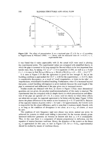
Figure 3.24 The effect of pressurization p on a tensioned pipe (T # 0) for u = 0 according
to Naguleswaran & Williams (1968): -, theory with the measured value of u = 0.312; 0, +,
experimental data.
it was found that A varies appreciably with 7, the actual A(g) were used in plotting
the experimental points. The experimental values are compared with simplified theory, in
which the pipe is assumed to be long enough for flexural effects to be less important than
tensile ones; thus, by taking v2q” >> q’”’ +. 0 in equations (3.100), as well as u = 0 and
6 = 1, it is easy to find %e(wl)/%e(wl)o = %e(f2~)/%e(~~)~ - n(l - 2~)/r]’/~.
[I
=
It is seen in Figure 3.24 that the agreement is good for low enough L’, but as the
buckling condition is approached (for L’/r = 2.66 for the experimental u = 0.312), there
is considerable discrepancy, as a result of ‘small irregularities, or kinks in the tube’, i.e.
imperfections, which lead to localized buckling. Furthermore, when I7 is increased beyond
that point, overall buckling (divergence) is never realized, because the axial length of the
pipe is constrained and deflection of the pipe gives rise to increased tension.
Similar results are obtained with flow, as shown in Figure 3.25(a); since dimensional
quantities are not given, the peculiar nondimensionalization of this study is retained. The
experimental data are compared with (i) simple theory in which pressurization and dilata-
tion of the pipe are ignored (I7 = 0, A = const.) and (ii) theory in which these effects
are taken into account. As expected, agreement is far better with the latter. Figure 3.25(b)
shows the phase difference in the motion at two locations (6 = 0.175 and 0.815). Because
of the opposite rotation of points with < 0.5 and > 0.5 approximately, the Coriolis term
is responsible for this phase difference, and it is seen that it increases nearly linearly with
u, so long as the condition of divergence is not close; at u = U,.d, of course, y? must
be zero.
The condition of zero frequency (and zero phase) was never, indeed can never, be
achieved for systems in which axial sliding is prevented, for the reasons already given:
increased deflection generates an increase in tension and thus w1 = 0 is unattainable.
Thus, in this case there is a component of tension proportional to deflection, and the
equation of motion becomes nonlinear. Hence, the dynamics of the system as the linear
Ucd is approached (in this case, as seen in Figure 3.25, for u > 0.5uCd approximately)
should be studied by means of nonlinear theory.