
Page 169 - Fluid-Structure Interactions Slender Structure and Axial Flow (Volume 1)
P. 169
PIPES CONVEYING FLUID: LINEAR DYNAMICS I 151
90 7
80 ' I 1
Flutter boundaries
N
-5 0 10 15 20 25
(b) 9
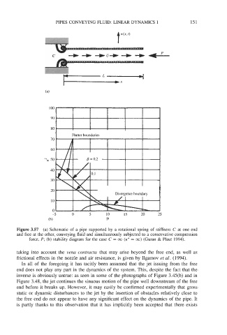
Figure 3.57 (a) Schematic of a pipe supported by a rotational spring of stiffness C at one end
and free at the other, conveying fluid and simultaneously subjected to a conservative compression
force, P; (b) stability diagram for the case C = 00 (K* = 00) (Guran & Plaut 1994).
taking into account the vena contractu that may arise beyond the free end, as well as
frictional effects in the nozzle and air resistance, is given by Ilgamov et al. (1994).
In all of the foregoing it has tacitly been assumed that the jet issuing from the free
end does not play any part in the dynamics of the system. This, despite the fact that the
inverse is obviously untrue: as seen in some of the photographs of Figure 3.45(b) and in
Figure 3.48, the jet continues the sinuous motion of the pipe well downstream of the free
end before it breaks up. However, it may easily be confirmed experimentally that gross
static or dynamic disturbances to the jet by the insertion of obstacles relatively close to
the free end do not appear to have any significant effect on the dynamics of the pipe. It
is partly thanks to this observation that it has implicitly been accepted that there exists