
Page 215 - Fluid-Structure Interactions Slender Structure and Axial Flow (Volume 1)
P. 215
PIPES CONVEYING FLUID: LINEAR DYNAMICS I1 197
made in Section 3.3.2 for uniform pipes are also made here, namely that motions are
small, the flow is fully developed turbulent, the curvature of flow trajectories is small,
etc. It is also assumed that (i) the profile of the axial component of the flow velocity, Uj,
is uniform, and (ii) there are no significant secondary flows, other than that associated
with changes in the cross-sectional flow area of the tubular beam. For simplicity, the
flow velocity is assumed not to be time-varying. The subscript i, as in U;, is added for
two reasons: (a) since there is also an external fluid, to distinguish internal- and external-
fluid properties, e.g. the densities pi and pe; (b) to facilitate the analysis in Chapter 8
(Volume 2) of the same system but with the outer fluidflowing with mean velocity, Up.
In the following, the rate of change of the momentum of the flow associated with
motions of the pipe will be derived first. This is then used in a Newtonian derivation of
the equation of motion.
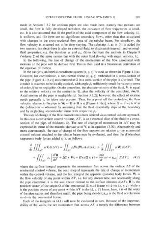
In the analysis, an inertial coordinate system (x, y, z) is used, as shown in Figure 4.l(a).
However, for convenience, a non-inertial frame {c, q, {} embedded in a cross-section of
the pipe [Figure 4.l(b,c)] and centered at 0 in a cross-section of the pipe is also used. The
conduit is assumed to be locally conical, with angle pi sufficiently small for velocity terms
of order 6’ to be negligible. On the centreline, the absolute velocity of the fluid, Y, is equal
to the relative velocity on the centreline, Ui, plus the velocity of the centreline, aw/at.
Axial motion of the pipe is negligible (cf. Section 3.3.2); however, the effect of rotation
needs generally to be taken into account. Thus, for a point off the centreline, the flow
velocity relative to the pipe is Wi = U, + 52 x fl [Figure 4.l(c)], where L? = at in
the <-direction - obtained by assuming that the fluid essentially slips at the boundary
and by neglecting second-order terms with respect to pi.
The rate of change of the flow momentum is here derived via a control volume approach.
In this case a convenient control volume, AQ, is an elemental slice of the fluid in a cross-
section of the pipe, of thickness a$. The rate of change of momentum in AT may be
expressed in terms of the material derivative of l$ as in equation (3.30). Alternatively and
more conveniently, the rate of change of the flow momentum relative to the noninertial
control volume attached to the tubular beam may be evaluated, and then the d’Alembert
(apparent) body forces added to it, as follows:
where the surface integral represents the momentum flux across the surface AS of the
noninertial control volume, the next integral represents the rate of change of momentum
within the control volume, and the last integral the apparent (pseudo) body forces. W; is
the flow velocity of any point within AT, Le. for any stream tube, not necessarily along
the pipe centreline; n is the unit vector normal to the surface element d(AS). R is the
position vector of the origin 0 of the noninertial {t, q, {) frame vis-u-vis (x, y, z), while r
is the position vector of any point within AQ in the [c, q, {) frame; here, r is of the order
of the pipe radius and therefore small, the pipe being slender; arel is the fluid acceleration
visd-vis the noninertial frame.
Each of the integrals in (4.1) will now be evaluated in turn. Because of the imperme-
ability of the walls, the net momentum flux across AS is merely the difference between