
Page 330 - Forensic Structural Engineering Handbook
P. 330
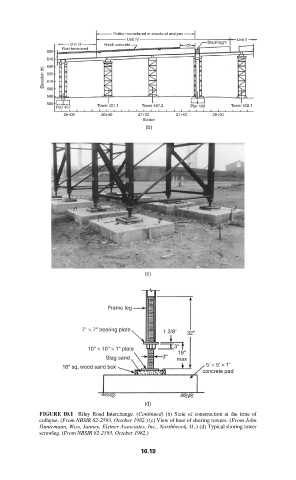
Portion considered in structural analysis
                                        Unit IV                      Unit V
                        Unit III  Fresh concrete       20'   Diaphragm
                      Post-tensioned
                  650
                  640
                  630
                 Elevation (ft)  620
                  610
                  600
                  590
                  580           Tower 407.1  Tower 407.2           Tower 408.1
                    Pier 407                             Pier 408
                       26+00     26+50    27+00      27+50    28+00
                                            Station
                                             (b)


                                            (c)


                                  Frame leg

                           7'' × 7'' bearing plate
                                                 1 3/8''  32''
                                                    3''
                             10'' × 10'' × 1'' plate
                                                     19''
                                  Slag sand      3''  max
                      16'' sq. wood sand box                 5' × 5' × 1'
                                                            concrete pad


                                            (d)
                FIGURE 10.1  Riley Road Interchange. (Continued) (b) State of construction at the time of
                collapse. (From NBSIR 82-2593, October 1982.) (c) View of base of shoring towers. (From John
                Duntemann, Wiss, Janney, Elstner Associates, Inc., Northbrook, IL.) (d) Typical shoring tower
                screwleg. (From NBSIR 82-2593, October 1982.)

                                           10.19