
Page 334 - Forensic Structural Engineering Handbook
P. 334
TEMPORARY STRUCTURES IN CONSTRUCTION 10.23
(c)
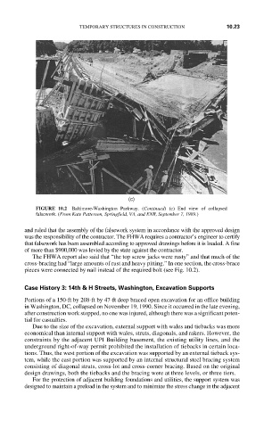
FIGURE 10.2 Baltimore-Washington Parkway. (Continued) (c) End view of collapsed
falsework. (From Kate Patterson, Springfield, VA, and ENR, September 7, 1989.)
and ruled that the assembly of the falsework system in accordance with the approved design
was the responsibility of the contractor. The FHWA requires a contractor’s engineer to certify
that falsework has been assembled according to approved drawings before it is loaded. A fine
of more than $900,000 was levied by the state against the contractor.
The FHWA report also said that “the top screw jacks were rusty” and that much of the
cross-bracing had “large amounts of rust and heavy pitting.” In one section, the cross-brace
pieces were connected by nail instead of the required bolt (see Fig. 10.2).
Case History 3: 14th & H Streets, Washington, Excavation Supports
Portions of a 150-ft by 208-ft by 47-ft deep braced open excavation for an office building
in Washington, DC, collapsed on November 19, 1990. Since it occurred in the late evening,
after construction work stopped, no one was injured, although there was a significant poten-
tial for casualties.
Due to the size of the excavation, external support with wales and tiebacks was more
economical than internal support with wales, struts, diagonals, and rakers. However, the
constraints by the adjacent UPI Building basement, the existing utility lines, and the
underground right-of-way permit prohibited the installation of tiebacks in certain loca-
tions. Thus, the west portion of the excavation was supported by an external tieback sys-
tem, while the east portion was supported by an internal structural steel bracing system
consisting of diagonal struts, cross-lot and cross-corner bracing. Based on the original
design drawings, both the tiebacks and the bracing were at three levels, or three tiers.
For the protection of adjacent building foundations and utilities, the support system was
designed to maintain a preload in the system and to minimize the stress change in the adjacent