Page 338 - Forensic Structural Engineering Handbook
P. 338

10.26                    CAUSES OF FAILURES

               4 spaces @ 7'-6" C-C  10 spaces @ 8'-0" C-C
                   30'-0"                 80'-0"
             14  15  16  17  18  19  20  21  22  23  24  25  26  27  28  Varies
                                                                     29
           N
                                W14 159*                             30
                                                                         24'-0"  3 spaces @ 8'-0" C-C
                                  W18 106
                                                                     31
                               HP14 73 (typ)
                                      W14 99
                                       W14 90                        32
                                          HP14 73                    33
                                      HP10 42* (typ)                 34
                                                                     35

                                                                     36
                                                       W18 106
                                                                     37
                                HP10 42 (typ)           W27 146      38  77'-0" 11 spaces @ 7'-0" C-C

                                                                     39
                               W12 53 (typ)
                                                                     40
                                                      W18 106        41
                                                  W14 90             42
                                                                     43
                                         HP14 73                     44
                                       W14 90
                                                                     45
                                                                        40'-0" 5 spaces @ 8'-0" C-C
                                   HP14 89
                                                                     46
                                  W18 106
                               W18 106 (typ)                         47
                                                                     48
             63  62  61  60  59  58  57  56  55  54  53  52  51  50  49
                                                                    Varies
               4 spaces @ 7'-6" C-C     10 spaces @ 8'-0" C-C
                   30'-0"                   80'-0"
                                          (d)
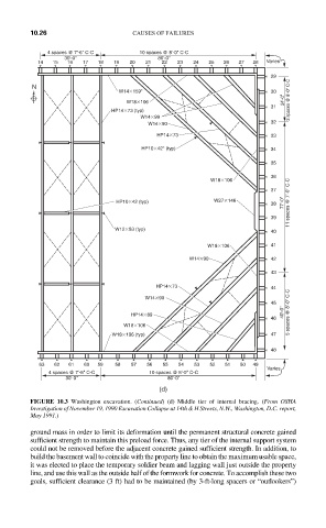
           FIGURE 10.3 Washington excavation. (Continued) (d) Middle tier of internal bracing. (From OSHA
           Investigation of November 19, 1990 Excavation Collapse at 14th & H Streets, N.W., Washington, D.C. report,
           May 1991.)

           ground mass in order to limit its deformation until the permanent structural concrete gained
           sufficient strength to maintain this preload force. Thus, any tier of the internal support system
           could not be removed before the adjacent concrete gained sufficient strength. In addition, to
           build the basement wall to coincide with the property line to obtain the maximum usable space,
           it was elected to place the temporary soldier beam and lagging wall just outside the property
           line, and use this wall as the outside half of the formwork for concrete. To accomplish these two
           goals, sufficient clearance (3 ft) had to be maintained (by 3-ft-long spacers or “outlookers”)
   333   334   335   336   337   338   339   340   341   342   343