
Page 484 - Forensic Structural Engineering Handbook
P. 484
MASONRY STRUCTURES 13.29
Architectural Failures
Water Permeance. Water permeance is the leading cause of masonry’s failure to perform
as intended. Water damage may include dimensional change, corrosion, decay, florescence,
freeze-thaw spalling or splitting, increased heat transmission, condensation, deterioration
of interior finishes and building contents, and tenant inconvenience.
Four inches of unit masonry, no matter how built, by whom, or of what material, never
stopped a wind-driven rain. Rain does not permeate through masonry units or mortar in sig-
nificant quantities. It enters through cracks between units and mortar. Figure 13.2 shows
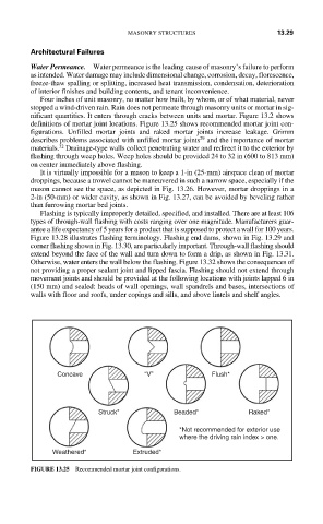
definitions of mortar joint locations. Figure 13.25 shows recommended mortar joint con-
figurations. Unfilled mortar joints and raked mortar joints increase leakage. Grimm
29
describes problems associated with unfilled mortar joints and the importance of mortar
32
materials. Drainage-type walls collect penetrating water and redirect it to the exterior by
flashing through weep holes. Weep holes should be provided 24 to 32 in (600 to 813 mm)
on center immediately above flashing.
It is virtually impossible for a mason to keep a 1-in (25-mm) airspace clean of mortar
droppings, because a trowel cannot be maneuvered in such a narrow space, especially if the
mason cannot see the space, as depicted in Fig. 13.26. However, mortar droppings in a
2-in (50-mm) or wider cavity, as shown in Fig. 13.27, can be avoided by beveling rather
than furrowing mortar bed joints.
Flashing is typically improperly detailed, specified, and installed. There are at least 106
types of through-wall flashing with costs ranging over one magnitude. Manufacturers guar-
antee a life expectancy of 5 years for a product that is supposed to protect a wall for 100 years.
Figure 13.28 illustrates flashing terminology. Flashing end dams, shown in Fig. 13.29 and
corner flashing shown in Fig. 13.30, are particularly important. Through-wall flashing should
extend beyond the face of the wall and turn down to form a drip, as shown in Fig. 13.31.
Otherwise, water enters the wall below the flashing. Figure 13.32 shows the consequences of
not providing a proper sealant joint and lipped fascia. Flashing should not extend through
movement joints and should be provided at the following locations with joints lapped 6 in
(150 mm) and sealed: heads of wall openings, wall spandrels and bases, intersections of
walls with floor and roofs, under copings and sills, and above lintels and shelf angles.
Concave “V” Flush*
Struck* Beaded* Raked*
*Not recommended for exterior use
where the driving rain index > one.
Weathered* Extruded*
FIGURE 13.25 Recommended mortar joint configurations.