
Page 204 - T. Anderson-Fracture Mechanics - Fundamentals and Applns.-CRC (2005)
P. 204
1656_C004.fm Page 184 Thursday, April 21, 2005 5:38 PM
184 Fracture Mechanics: Fundamentals and Applications
Combining Equation (4.16)–(4.20) with Equation (2.51) gives
t
K 2 ()
V
t
G() = A ( ) I (4.21)
E′
where
V −1
AV() ≈ − 1 ( − hV) (4.22)
1
c
r
Thus the relationship between K and G depends on crack speed. A more accurate (and more
I
complicated) relationship for A(V ) is given in Appendix 4.1.
When the plastic zone ahead of the propagating crack is small, K (t) uniquely defines the
I
crack-tip stress, strain, and displacement fields, but the angular dependence of these quantities
is different from the quasistatic case. For example, the stresses in the elastic singularity zone are
given by [32, 33, 35]
Kt()
σ = I f θ V (, ) (4.23)
ij
2 πr ij
The function f reduces to the quasistatic case (Table 2.1) when V = 0. Appendix 4.1 outlines the
ij
derivation of Equation (4.23) and gives specific relationships for f in the case of rapid crack
ij
propagation. The displacement functions also display an angular dependence that varies with V.
Consequently, α and α in Equation (4.9) must depend on crack velocity as well as position, and
y
x
the Mott analysis is not rigorously correct for dynamic crack propagation.
4.1.2.3 Dynamic Toughness
As Equation (4.15) indicates, the dynamic stress intensity is equal to K , the dynamic material
ID
resistance, which depends on crack speed. This equality permits experimental measurements of K .
ID
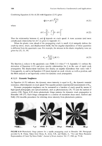
Dynamic propagation toughness can be measured as a function of crack speed by means of
high-speed photography and optical methods, such as photoelasticity [36, 37] and the method of
caustics [38]. Figure 4.10 shows photoelastic fringe patterns for dynamic crack propagation in
Homalite 100 [37]. Each fringe corresponds to a contour of maximum shear stress. Sanford and
Dally [36] describe procedures for inferring stress intensity from photoelastic patterns.
FIGURE 4.10 Photoelastic fringe patterns for a rapidly propagating crack in Homalite 100. Photograph
provided by R. Chona. Taken from Chona, R., Irwin, G.R., and Shukla, A., “Two and Three Parameter
Representation of Crack Tip Stress Fields.” Journal of Strain Analysis, Vol. 17, 1982, pp. 79–86.